The structural analysis software RFEM 6 is the basis of a modular software system. The main program RFEM 6 is used to define structures, materials, and loads of planar and spatial structural systems consisting of plates, walls, shells, and members. The program also allows you to create combined structures as well as to model solid and contact elements.
RSTAB 9 is a powerful analysis and design software for 3D beam, frame, or truss structure calculations, reflecting the current state of the art and helping structural engineers meet requirements in modern civil engineering.
Do you often spend too long calculating cross-sections? Dlubal Software and the RSECTION stand-alone program facilitate your work by determining section properties of various cross-sections and performing a subsequent stress analysis.
Do you always know where the wind is blowing from? From the direction of innovation, of course! With RWIND 2, you have a program at your side that uses a digital wind tunnel for the numerical simulation of wind flows. The program simulates these flows around any building geometry and determines the wind loads on the surfaces.
Are you looking for an overview of snow load zones, wind zones, and seismic zones? Then you are in the right place. Use the Geo-Zone Tool to determine quickly and efficiently snow loads, wind speeds, and seismic data according to ASCE 7‑16 and other international standards.
Would you like to try out the capabilities of the Dlubal Software programs? You have the opportunity to do so! The free 90-day full version allows you to thoroughly test all our programs.
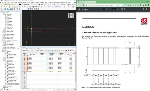
Corrugated web beams allow for further optimization of steel structures. They are often used to reduce the self-weight of main load-bearing elements and to prevent buckling failure of webs due to the corrugation.
This example will be based on a WTA – 1250 – 300x20 Beam from the Zeman catalogue.
To create a model of this beam, it's best to start by modeling a sine wave that will be used to edit the web. This consists of the steps shown below and in the attached images.
After these steps, it's recommended to create a parametric section with the dimensions of the corrugated beam. Members using this section can later be transformed into surfaces.
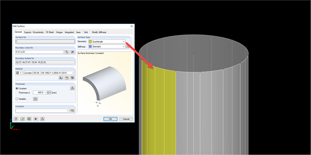
With this set of surfaces, it is recommended to copy the sine spline into the position of the top and bottom edge of the surface representing the web.Later, it is required to change the geometry type of the web surface to Quadrangle and redefine the boundary lines of this element.
After preparing the geometry, it's required to focus on finishing the model for the calculation. Select the start and end lines of the member and create a member with the type Rigid. After that, it's possible to define nodal supports on the beam and loads in the model. In order to check the resulting internal forces of a member, it is recommended to define a result beam on the main center line. Finishing all of these steps allows us to start the analysis of the beam.
Remember to define proper mesh settings with an adequate target length of the finite elements and to use a line mesh refinement on the sine lines.
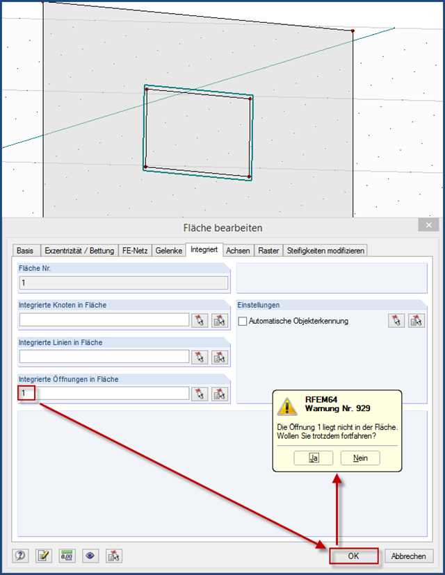
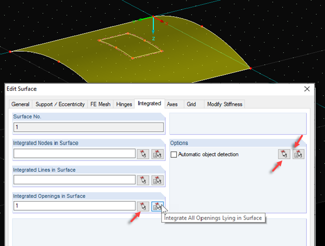
This is most likely due to the quadrangle surfaces you created. In the case of curved surfaces, it is not possible to automatically integrate the objects that rest in the surface.
However, you can integrate them into the surfaces manually. Tips for this can be found in the linked technical article.
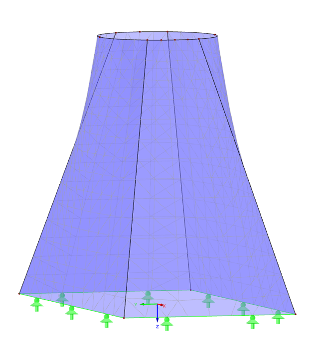
It is then necessary to integrate the lines of the reinforcement ring into the quadrangle surface of the chimney. Otherwise, the elements are not connected to each other.
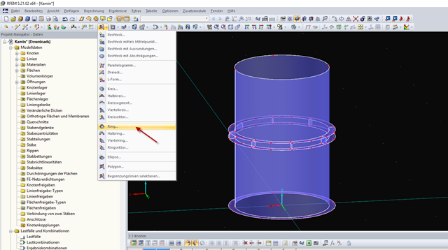
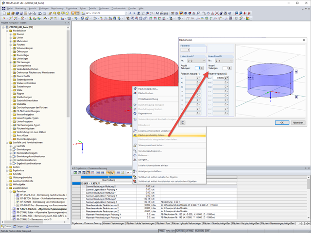
Yes, this is possible. Silos/tanks are usually made up of one curved 2D surface. This 2D surface needs to be split into two separate 2D surfaces for the cylinder to be exported into Revit. If it is only made up of one surface, then only half of the cylinder will be exported.
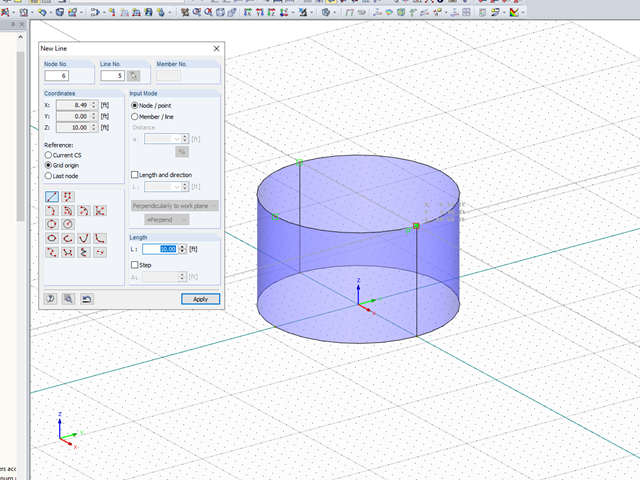
To do this, create a cylinder with one single surface. Then draw a line exactly adjacent to the original line that was created perpendicular to the top and bottom of the cylinder.
Next, delete the surface and recreate two surfaces using the quadrangle tool.
This process is also demonstrated in the attached video.
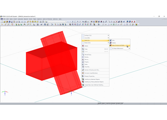
There is an option to convert an intersection to a line. This option allows you to create the intersection manually. Here is an example:
1. First, an intersection between two objects is created, here using the "New Compound Solid" command:
In this specific case, the cylinder is subtracted from the cuboid, thus creating an intersection:
2. This intersection is now "converted into lines". For this, select all involved objects and in the shortcut menu, select "Convert into Line" under "Intersection":
3. The new lines are used to create new surfaces or modify existing ones. You can change the boundary lines of a surface by selecting them again. In particular, the intersection area must be modeled as a quadrangle surface:
4. Finally, it is necessary to create the solid again:
If you have modeled your pipe surface as a quadrangle surface, you can achieve this by splitting the surface at least once.
Then, define a new average region for the surface by selecting the center, defining the dimension, specifying the vector, and determining the averaging type you want.
You can easily define the vector by picking two points.
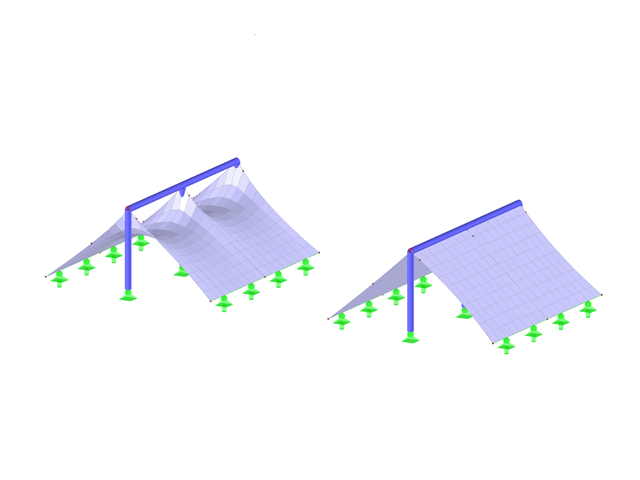
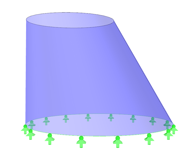
Rotated surfaces are often used in RFEM to model and calculate geometrical conditions easily. However, if you use a large number of rotated surfaces in the model, you may experience performance drop. This is due to the definition of the surfaces, because they have to be generated in the background again and again using the boundary conditions if a change occurs in the structural system.
Therefore, we recommend replacing the rotated surfaces with surfaces of the "Quadrangle" type, which significantly reduce the amount of data. Furthermore, quadrangle surfaces also allow you to apply loads to parts of the surface only.